Welcome to the official website of Luoyang AISITE Transformer Co., LTD


Exploring Transformers: From Coils to Cores
Release time:
Feb 28,2025
Source:
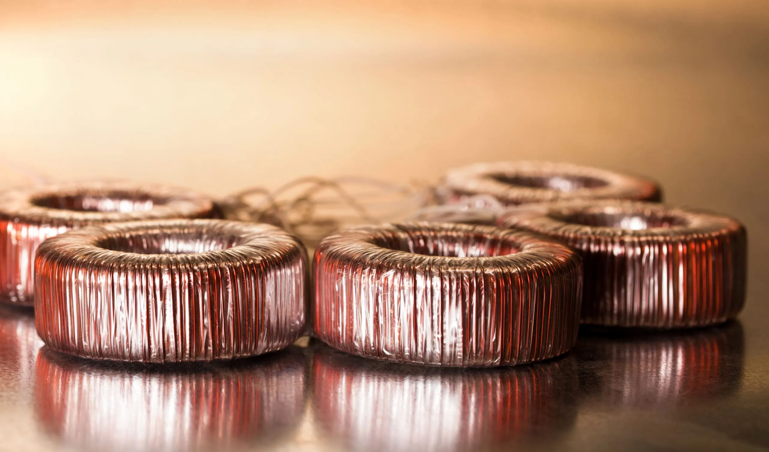
A transformer is a device that uses the principle of electromagnetic induction to convert alternating voltage. Its main components include the primary coil, secondary coil and iron core.
In the field of electronics, transformers are often found, most often used as voltage converters and insulators in power supplies.
Simply put, the ratio of stresses of primary and secondary coils is equal to the coefficient of turns of the primary and secondary coils. Thus, for the output of various stresses, a change in the coefficient of rotation of the coil can be achieved.
Depending on the various working frequencies of their transformers, as a rule, they can be divided into low -frequency transformers and high -frequency transformers. For example, in everyday life, the frequency of alternating current of industrial frequency is 50 Hz, and we call transformers operating at this frequency, low -frequency transformers; The operating frequency of high -frequency transformers can reach tens of up to hundreds of kHz.
A low -frequency transformer with the same output power has a much smaller volume compared to a high -frequency transformer.
Transformers are relatively large components in power chains. To provide the output power while maintaining a small volume, high -frequency transformers are used, so high -frequency transformers are usually used in pulsed power sources.
The principle of operation of high -frequency transformers and low -frequency transformers is the same, both use the principle of electromagnetic induction, but the materials used for their “cores” are different.
The iron core of low -frequency transformers usually consists of many sheets of silicon steel, while the iron core of high -frequency transformers consists of high -frequency magnetic materials (such as ferrite). (Therefore, the iron core of high -frequency transformers is usually called a magnetic core)
In power circuits adjusted to direct current, low -frequency transformers transmit sinusoidal wave signals.
In the circuits of the pulsed power source, high -frequency transformers transmit high -frequency pulsed rectangular signals.
A low -frequency transformer is usually on an electronic symbol. The primary coil has only one winding. The symbol that you often see is this:
On an electronic symbol of a high -frequency transformer, can you find that there are two coils on the primary side of some high -frequency transformers?
In fact, there are no two primary coils. There is only one primary coil, and the other is an auxiliary coil. The “auxiliary coil” actually belongs to the secondary coil, and it is called an auxiliary coil, because it plays an auxiliary role in the chain.
The auxiliary coil serves the chain connecting the primary coil. At the initial level, an auxiliary coil may provide a voltage source and a feedback signal to protect the transformer. Thanks to the feedback effect of an auxiliary coil, the internal power source may be stabilized.
In addition, when the output of the secondary coil is overloaded, excessive current can lead to insufficient bearing capacity of the secondary coil, which leads to a decrease in the output voltage of the secondary coil and a decrease in the output voltage of the auxiliary coil. When the voltage drops to a certain extent, this prevents the launch of the oscillatory circuit, thereby protecting the switch tube.
The ratio between the output power and the input power of the transformer with rated power is called the effectiveness of the transformer,
When the output power of the transformer is equal to the input power, the efficiency is 100%. In fact, such a transformer does not exist, because there will be certain losses due to the presence of copper and iron losses in the transformer.
keyword:
Previous page:
Next page
Previous page:
Next page
RELATED NEWS