Welcome to the official website of Luoyang AISITE Transformer Co., LTD


Transformer Maintenance Guide: Operation Procedures, Common Faults & Troubleshooting Solutions
Release time:
Jun 24,2025
Source:
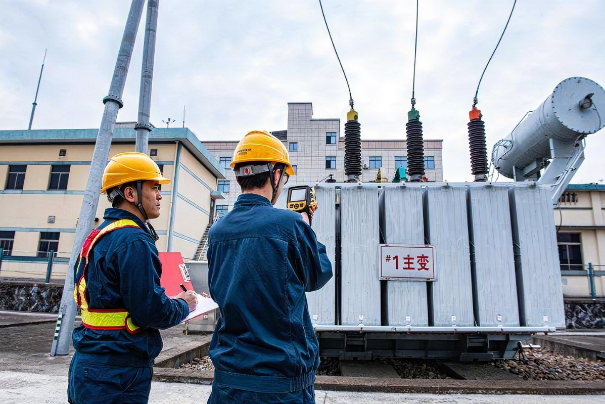
Transformers are static electrical devices operating on the principle of electromagnetic induction. They convert AC electrical energy of one voltage, current, or phase configuration into another with the same frequency, enabling voltage transformation, current adjustment, impedance matching, and electrical isolation. Widely used across industries, transformers demand proper operation and maintenance. This guide covers key procedures and troubleshooting methods for common faults.
I. Transformer Operation
1. Pre-Operation Inspection
Check Fasteners & Connections:
Tighten all bolts, wiring, busbars, and connecting rods.
Caution: Avoid excessive torque on copper nuts to prevent thread stripping.
Use dissimilar metals for stainless-steel bolt/nut pairs (e.g., bronze nut) to avoid seizing.
Verify Component Installation:
Ensure all parts removed during shipping are reinstalled.
Inspect for debris inside the transformer (especially cooling ducts). Remove dust buildup.
Clear all temporary installation tools/materials.
Inspect Wiring:
Ensure temperature controller wires do not contact coils/live parts. Secure them to the enclosure if needed.
Test Auxiliary Devices:
Confirm fans, temperature controllers, and monitors function properly.
For 3-phase fans: Verify rotation direction (airflow should enter coils from the bottom). Reverse phase sequence if incorrect.
Follow manufacturer guidelines for temperature controller wiring.
2. Pre-Operation Testing
Perform these 5 key tests (adjust for site constraints):
DC resistance measurement (all tap positions)
Voltage ratio test and vector group verification
Core-to-clamp insulation test
Winding insulation resistance test
Applied power-frequency withstand voltage test
Note: For used transformers, apply 80% of factory test voltage for withstand testing.
3. Safety Precautions
⚠️ Critical:
Verify grounding system reliability before energization.
Install safety barriers around open-type transformers.
Never touch live transformer components.
Only qualified personnel may install, test, or maintain transformers.
4. Energization & Operation
Startup Sequence:
For units with temperature controllers: Energize the transformer first, then activate the controller after calibration.
Inrush Current Management:
Close breakers at no-load. Inrush peaks can reach 10–15× rated current. Set protection relays above this peak.
Load Application:
Gradually increase load from low to high. Monitor for abnormal noise. Avoid sudden full-load switching.
Re-energization After Shutdown:
Usually requires no special steps.
If condensation occurs (high humidity), dry the transformer before restarting.
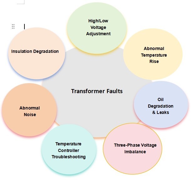
II. Common Transformer Faults & Solutions
Accurate fault diagnosis and timely action ensure operational safety. Key fault categories:
Thermal Faults: Local hotspots or overall overheating
Electrical Faults: Partial discharge, arcing, sparking
Insulation Faults: Breakdown or degradation
Other Faults: Abnormal noise, protection malfunctions, oil leaks
Diagnostic Methods
Visual Inspection: Load currents, oil color, physical damage
Auditory Check: Unusual hum, buzzing, or cracking sounds
Testing: Measure DC resistance, insulation resistance
1. Insulation Degradation
Testing Conditions: 10–40°C, humidity ≤85%; use 2500V megger.
Minimum Insulation Resistance:
| Component | 10kV System | 35kV System |
|---|---|---|
| HV-LV & Ground | ≥300 MΩ | ≥1000 MΩ |
| LV-Ground | ≥100 MΩ | |
| Core-Clamps & Ground | ≥2 MΩ | |
| Clamping Bolts & Ground | ≥2 MΩ |
Guidelines:
Acceptable: ≥2 MΩ per 1000V rating at 25°C.
If condensation occurs, dry the transformer before operation—regardless of insulation readings.
Core-to-ground resistance ≥0.1 MΩ is acceptable; dry if lower.
2. High/Low Voltage Adjustment
Example: 10,000V ±2×2.5% transformer taps:
10,500V | 2. 10,250V | 3. 10,000V | 4. 9,750V | 5. 9,500V
Adjustment Procedure:
Measure secondary voltage (pre-adjustment).
Identify transformer’s tap range and current position.
Calculate required tap using voltage ratio:
Example: Output = 420V, Tap 3 → Grid voltage = 420 × (10,000/400) = 10,500V → Switch to Tap 1.
For oil transformers: Cycle tap changer 3–5 times before setting.
Measure post-adjustment DC resistance. Verify phase imbalance ≤2%.
3. Abnormal Temperature Rise
Diagnostic Steps:
Verify temperature controller/sensor accuracy.
Check cooling fans and ventilation.
Review loading and sensor placement.
If temperature rises under normal load → Internal fault. De-energize and inspect.
Common Causes:
Short-circuited windings/turns, loose contacts
Core short-circuits, damaged clamping bolt insulation
Tank heating due to stray currents/eddy losses
Chronic/accidental overloading
Blocked cooling paths
4. Abnormal Noise
Internal Sources:
Loose core: "Clanking" or "humming"
Ungrounded core: Faint "crackling" discharges
Poor contacts: "Hissing" or "popping" (intensifies with load)
Discharging leads: "Snapping" sounds
Dirty bushings: "Sizzling"
External Sources:
Overload: Heavy "hum"
High voltage: Sharp "buzz"
Phase loss: High-pitched noise
System resonance: Irregular "roar"
LV short-circuit/ground: Loud "groaning"
Loose connections: Arcing/sparking
5. Temperature Controller Troubleshooting
| Symptom | Action |
|---|---|
| No display | Check power supply, fuses, terminal connections |
| "OP" error (missing temp) | Verify PT100 sensor insertion; test resistance (≈110Ω at 0°C) |
| Temperature deviation | Inspect sensor placement, resistance, EMI sources, or calibration |
| Communication failure | Test cabling; contact supplier if persistent |
6. Three-Phase Voltage Imbalance
Causes & Solutions:
Ground Faults:
Metallic grounding: Fault phase ≈0V, healthy phases ↑√3×
Non-metallic: Fault phase ↓, healthy phases slightly ↑
Load Imbalance:
Neutral wire break → Voltage drift
Severe imbalance → Overloaded phase ↓ voltage
Mitigation:
Implement multi-point grounding for neutral conductors.
Use single-phase transformers in predominantly single-phase load areas.
Regularly measure and balance transformer loads.
7. Oil Degradation & Leaks
Darkened Oil: Indicates moisture/carbon contamination → Replace oil immediately.
Leaks: Caused by weld cracks, seal failure, vibration, corrosion, or impact.
Minor seepage (oil level normal): Schedule repair.
Major leak (visible oil loss): Shut down immediately. Repair and refill.
Contact us today for:
Free transformer health assessments
Tailored maintenance protocols
Rapid-replacement systems to minimize downtime
Reach our engineering experts:
📧 Email: [sale@aisite-ast.com]
📞 Phone: [+86 15896663407]
🌐 Website: [https://www.aisite-ast.com/]
Don’t let transformer failures halt your operations—partner with us in power stability.
keyword:
RELATED NEWS