Welcome to the official website of Luoyang AISITE Transformer Co., LTD


")
Cast resin transformer ( Dry type transformer)
These transformers are made with a magnetic core from laminated grain-oriented silicon steel. Additionally, HV winding can also be wound from insulated by an inter-layer film, pre-impregnated with heat-activated epoxy resin. The ends of the windings are protected and insulated using Class F materials. With outstanding resistance to harsh industrial atmospheres, excellent dielectric withstand and very good resistance to short-circuit conditions are ideal for industrial and commercial use.
keyword:
Cast resin transformer ( Dry type transformer)
DESCRIPTION
Specification
These transformers are made with a magnetic core from laminated grain-oriented silicon steel. Additionally, HV winding can also be wound from insulated by an inter-layer film, pre-impregnated with heat-activated epoxy resin. The ends of the windings are protected and insulated using Class F materials. With outstanding resistance to harsh industrial atmospheres, excellent dielectric withstand and very good resistance to short-circuit conditions are ideal for industrial and commercial use.
Features and Advantages
Cast resin dry type transformer up to 15 MVA - 36 kV.
Guaranteed against fire hazards.
Rated insulation level up to 36 kV
Rated frequency 50 or 60 Hz
MV windings encapsulated in cast resin
Pre-impregnated LV windings
Thermal insulation Class F
Resistance to high humidity levels > 95%
Naturally cooled (AN) or air forced (AF) on request
Indoor installation or outdoor on request (with enclosure up to IP20)
Safe and environment friendly
Reduced risk of failure in service
Optimized total cost of ownership (TCO)
Low maintenance cost
High short-time overload capacity
Crack-resistant
Compact design
Sustainable
Applications
lBuildings
lIndustry
lHospital
lFood and Beverage
Parameters
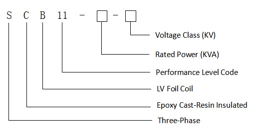
SCB11series 35KVcast resin transformer (dry type transformer)
Code and implication
Model | Rated power | Rated primary voltage | Tapping | Rated secondary voltage | Vector group | No-load losses | Load losses | No-load current | Rated impedance |
SCB11-50 | 50 | 35 | ±2×2.5 | 0.4 | Yyn0 | 450 | 1420 | 2.3 | 6.0 |
SCB11-100 | 100 | 35 | ±2×2.5 | 0.4 | Yyn0 | 630 | 2090 | 2.0 | 6.0 |
SCB11-160 | 160 | 35 | ±2×2.5 | 0.4 | Yyn0 | 790 | 2810 | 1.5 | 6.0 |
SCB11-200 | 200 | 35 | ±2×2.5 | 0.4 | Yyn0 | 880 | 3320 | 1.5 | 6.0 |
SCB11-250 | 250 | 35 | ±2×2.5 | 0.4 | Yyn0 | 990 | 3800 | 1.3 | 6.0 |
SCB11-315 | 315 | 35 | ±2×2.5 | 0.4 | Yyn0 | 1170 | 4510 | 1.3 | 6.0 |
SCB11-400 | 400 | 35 | ±2×2.5 | 0.4 | Yyn0 | 1370 | 5410 | 1.1 | 6.0 |
SCB11-500 | 500 | 35 | ±2×2.5 | 0.4 | Yyn0 | 1620 | 6650 | 1.1 | 6.0 |
SCB11-630 | 630 | 35 | ±2×2.5 | 0.4 | Yyn0 | 1860 | 7690 | 1.0 | 6.0 |
SCB11-800 | 800 | 35 | ±2×2.5 | 0.4 | Yyn0 | 2160 | 9120 | 1.0 | 6.0 |
SCB11-1000 | 1000 | 35 | ±2×2.5 | 0.4 | Yyn0 | 2430 | 1040 | 0.75 | 6.0 |
SCB11-1250 | 1250 | 35 | ±2×2.5 | 0.4 | Yyn0 | 2830 | 1270 | 0.75 | 6.0 |
SCB11-1600 | 1600 | 35 | ±2×2.5 | 0.4 | Yyn0 | 3240 | 1540 | 0.75 | 6.0 |
SCB11-2000 | 2000 | 35 | ±2×2.5 | 0.4 | Yyn0 | 3820 | 1820 | 0.75 | 6.0 |
SCB11-2500 | 2500 | 35 | ±2×2.5 | 0.4 | Yyn0 | 4450 | 2180 | 0.75 | 6.0 |
SCB11Series 10KVTransformer
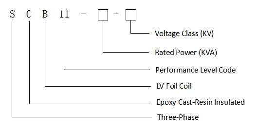
Code and implication
Rated power | Rated primary voltage | Tapping | Rated secondary voltage | Vector group | No-load losses | Load losses at different insulation classes | No-load current | Rated impedance | ||
130℃(B)(100℃) | 155℃(F)(120℃) | 180℃(H)(145℃) | ||||||||
30 | 6/6.3/6.6/10/10.5/11 | ±2.5 | 0.4 | Dyn11 | 0.19 | 0.67 | 0.71 | 0.76 | 2 | 4 |
50 | 6/6.3/6.6/10/10.5/11 | ±2.5 | 0.4 | Dyn11 | 0.27 | 0.94 | 1 | 1.07 | 2 | 4 |
80 | 6/6.3/6.6/10/10.5/11 | ±2.5 | 0.4 | Dyn11 | 0.37 | 1.29 | 1.38 | 1.48 | 1.5 | 4 |
100 | 6/6.3/6.6/10/10.5/11 | ±2.5 | 0.4 | Dyn11 | 0.4 | 1.48 | 1.57 | 1.69 | 1.5 | 4 |
125 | 6/6.3/6.6/10/10.5/11 | ±2.5 | 0.4 | Dyn11 | 0.47 | 1.74 | 1.85 | 1.98 | 1.3 | 4 |
160 | 6/6.3/6.6/10/10.5/11 | ±2.5 | 0.4 | Dyn11 | 0.54 | 2 | 2.13 | 2.28 | 1.3 | 4 |
200 | 6/6.3/6.6/10/10.5/11 | ±2×2.5 | 0.4 | Dyn11 | 0.62 | 2.37 | 2.53 | 2.71 | 1.1 | 4 |
250 | 6/6.3/6.6/10/10.5/11 | ±2×2.5 | 0.4 | Dyn11 | 0.72 | 2.59 | 2.76 | 2.96 | 1.1 | 4 |
315 | 6/6.3/6.6/10/10.5/11 | ±2×2.5 | 0.4 | Dyn11 | 0.88 | 3.27 | 3.47 | 3.73 | 1 | 4 |
400 | 6/6.3/6.6/10/10.5/11 | ±2×2.5 | 0.4 | Dyn11 | 0.98 | 3.75 | 3.99 | 4.28 | 1 | 4 |
500 | 6/6.3/6.6/10/10.5/11 | ±2×2.5 | 0.4 | Dyn11 | 1.16 | 4.59 | 4.88 | 5.23 | 1 | 4 |
630 | 6/6.3/6.6/10/10.5/11 | ±2×2.5 | 0.4 | Dyn11 | 1.34 | 5.53 | 5.88 | 6.29 | 0.85 | 4 |
630 | 6/6.3/6.6/10/10.5/11 | ±2×2.5 | 0.4 | Dyn11 | 1.3 | 5.61 | 5.96 | 6.40 | 0.85 | 6 |
800 | 6/6.3/6.6/10/10.5/11 | ±2×2.5 | 0.4 | Dyn11 | 1.52 | 6.55 | 6.96 | 7.46 | 0.85 | 6 |
1000 | 6/6.3/6.6/10/10.5/11 | ±2×2.5 | 0.4 | Dyn11 | 1.77 | 7.65 | 8.13 | 8.76 | 0.85 | 6 |
1250 | 6/6.3/6.6/10/10.5/11 | ±2×2.5 | 0.4 | Dyn11 | 2.09 | 9.1 | 9.69 | 10.3 | 0.85 | 6 |
1600 | 6/6.3/6.6/10/10.5/11 | ±2×2.5 | 0.4 | Dyn11 | 2.45 | 11.1 | 11.7 | 12.5 | 0.85 | 6 |
2000 | 6/6.3/6.6/10/10.5/11 | ±2×2.5 | 0.4 | Dyn11 | 3.05 | 13.6 | 14.4 | 15.5 | 0.7 | 6 |
2500 | 6/6.3/6.6/10/10.5/11 | ±2×2.5 | 0.4 | Dyn11 | 3.6 | 16.1 | 17.1 | 18.4 | 0.7 | 6 |
1600 | 6/6.3/6.6/10/10.5/11 | ±2×2.5 | 0.4 | Dyn11 | 2.45 | 12.2 | 12.9 | 13.9 | 0.85 | 8 |
2000 | 6/6.3/6.6/10/10.5/11 | ±2×2.5 | 0.4 | Dyn11 | 3.05 | 15 | 15.9 | 17.1 | 0.7 | 8 |
2500 | 6/6.3/6.6/10/10.5/11 | ±2×2.5 | 0.4 | Dyn11 | 3.6 | 17.7 | 18.8 | 20.2 | 0.7 | 8 |
Dimensions
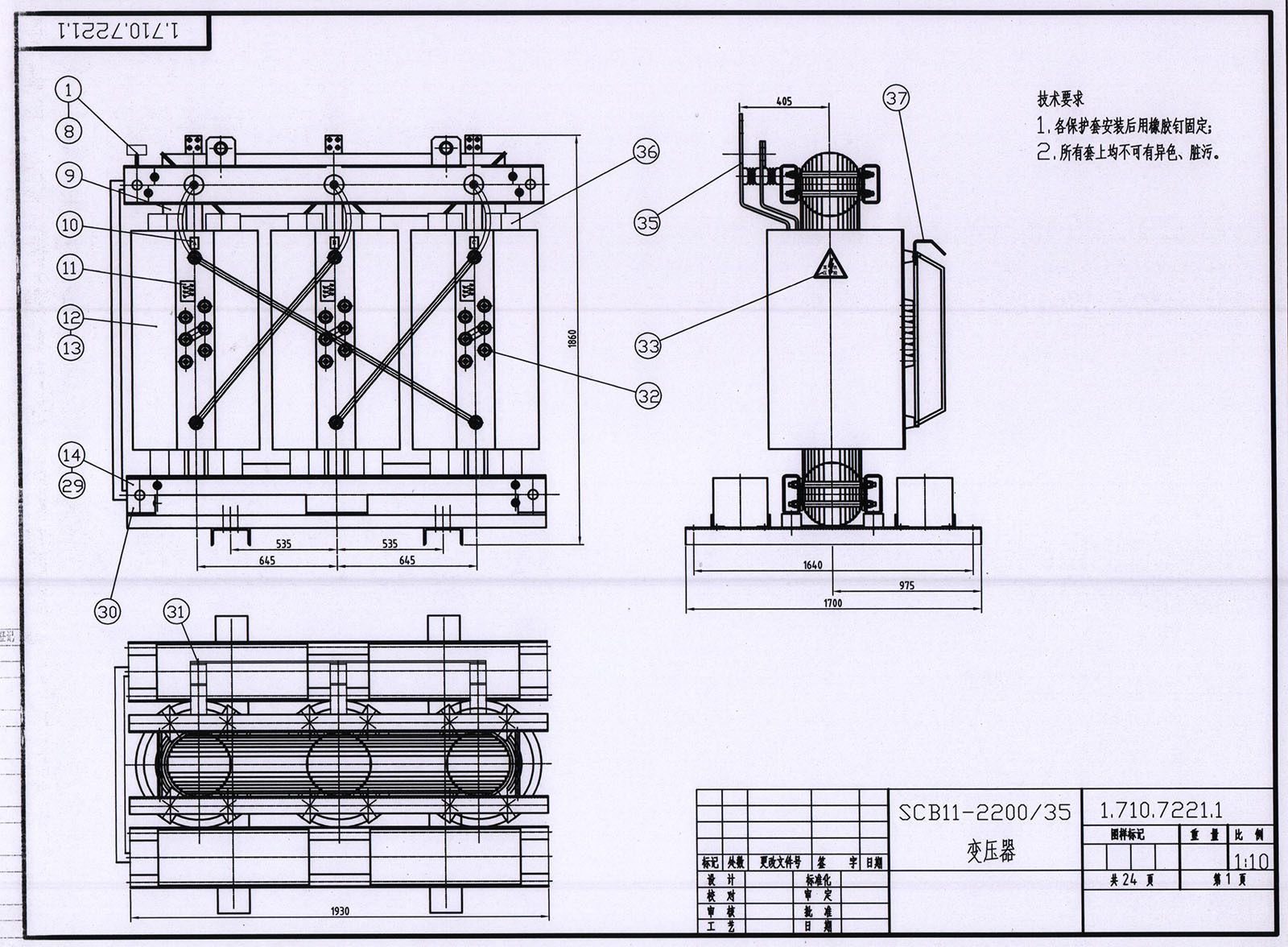
Note: Dimensions are for guidance and reference only and are NON CONTRACTUAL.
Logistic and service
Once the transformer is successfully tested and qualified, the product is ready for shipping either by truck or sea-freight.
As a manufacturer, we understand the relevance that logistics represents to our customers. This is one of the reasons why Aisite has developed a large and qualified net work of suppliers that have the same values and targets.
Aisite takes care of all official documentation, depending on final destinations and delivery terms.
Different packaging for special applications or conditions:
- Standard packing
- Crate packing
- Seaworthy packing
Built for sturdiness and efficiency(Production process)
The core
The iron core forms the central element of every transformer. High-grade, cold-rolled metal sheets are precision-cut using computer-controlled machines to ensure compliance with even the smallest tolerances. The individual sheets are then assembled into cores using the step-lap technique by our veteran workers. In this way, weachieve an especially good flux distribution at the joints, resulting in exceptionally low losses and minimal no-load noise.
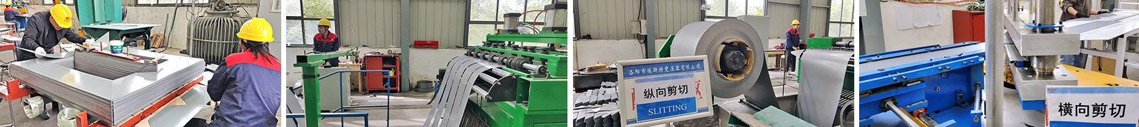
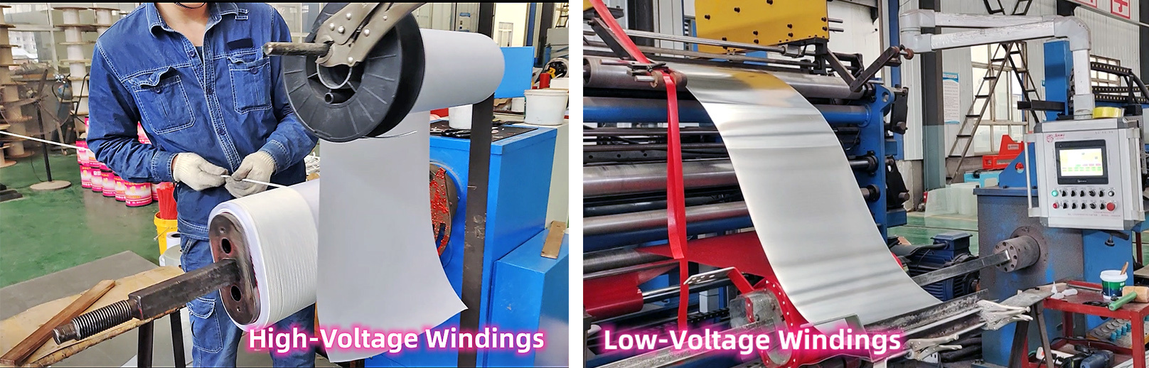
Windings
Transformer windings are subject to extremely high electrical and mechanical stresses and must therefore be protected. The transformer windings of our transformers are made of copper or aluminum. Low-voltage windings are made fromfoil, and high-voltage windings are manufactured from round orstripprofile wire. The use of insulating paper partially coated with epoxy resin (diamond-dotted paper) bonds the winding into a compact block during the drying process and additionally increases the short-circuit capacity.
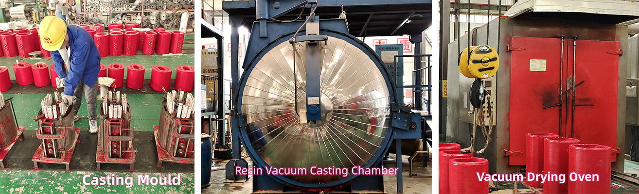
Encapsulation process
The encapsulation process is a key stage within the manufacturing process. Encapsulation is carried out under the most rigorous conditions in order to ensure optimum insulating and mechanical characteristics. The resin mix is prepared in a continuously monitored mixing plant where all the components are mixed together just before the encapsulation process. Inside the vacuum casting chamber, the resin is introduced into the mould. The components are mixed together just before the encapsulation process, this ensures that the viscosity of the resin when poured in the moulds is very low, filling interstices and allowing the finished winding to reach the lowest level of partial discharge. Once the casting is finished the coils are placed into the curing oven for the resin gel to cure, and acquire the optimal final electrical and mechanical properties.
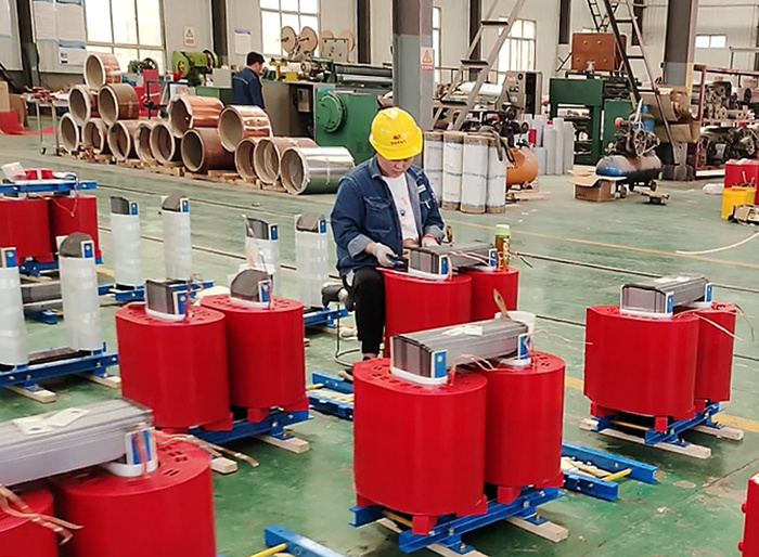
Final assembly
The transformer’s core-and-coil assembly consists of the core, windings, and connecting cables.
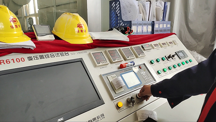
Testing
Ourtransformers are dispatched to the customer only after successfully passing the final inspection and testing. Ourfactory has a high-voltage test bay, where our veteranspecialists conduct a wide range of tests, from voltage tests and temperature-rise tests, to special tests for insulation resistance, partial discharge measurement, harmonics, and noise level. Short-circuit tests are performed in internationally recognized and approved institutes. Ourtests in accordance with the applicable standards and provides our customers with additional certificates on request.
For laboratory- or on-site measurements of partial discharge at medium-and high voltage components according GB/T 7354-2003, VDE 0434, IEC 60270, EN 50178, VDE 0884, IEC60747-5-5, UL 1577 and others.
Previous page
Next page
Previous page
Next page
Related products

Related products
Leave a message
Factory Address:500 meters southeast of Yilong Bridge in Yichuan, Luoyang, China