Welcome to the official website of Luoyang AISITE Transformer Co., LTD


10KV Oil Immersed Transformer
As a manufacturer, we understand the relevance that logistics represents to our customers. This is one of the reasons why Aisite has developed a large and qualified net work of suppliers that have the same values and targets.
keyword:
10KV Oil Immersed Transformer
Category:
DESCRIPTION
Code and implication

Model | Rated power | Rated primary voltage | Tapping | Rated secondary voltage | Vector group | No-load losses | Load losses | No-load current | Rated impedance | |
Dy | Yy | |||||||||
S13-M-30 | 30 | 6/6.3/10/10.5 | ±2×2.5 | 0.4 | Yyn0 | 80 | 630 | 600 | 2.3 | 4 |
S13-M-50 | 50 | 6/6.3/10/10.5 | ±2×2.5 | 0.4 | Yyn0 | 100 | 910 | 870 | 2 | 4 |
S13-M-63 | 63 | 6/6.3/10/10.5 | ±2×2.5 | 0.4 | Yyn0 | 110 | 1090 | 1040 | 1.9 | 4 |
S13-M-80 | 80 | 6/6.3/10/10.5 | ±2×2.5 | 0.4 | Yyn0 | 130 | 1310 | 1250 | 1.9 | 4 |
S13-M-100 | 100 | 6/6.3/10/10.5 | ±2×2.5 | 0.4 | Yyn0 | 150 | 1580 | 1500 | 1.8 | 4 |
S13-M-125 | 125 | 6/6.3/10/10.5 | ±2×2.5 | 0.4 | Yyn0 | 170 | 1890 | 1800 | 1.7 | 4 |
S13-M-160 | 160 | 6/6.3/10/10.5 | ±2×2.5 | 0.4 | Yyn0 | 200 | 2310 | 2200 | 1.6 | 4 |
S13-M-200 | 200 | 6/6.3/10/10.5 | ±2×2.5 | 0.4 | Yyn0 | 240 | 2730 | 2600 | 1.5 | 4 |
S13-M-250 | 250 | 6/6.3/10/10.5 | ±2×2.5 | 0.4 | Yyn0 | 290 | 3200 | 3050 | 1.4 | 4 |
S13-M-315 | 315 | 6/6.3/10/10.5 | ±2×2.5 | 0.4 | Yyn0 | 340 | 3830 | 3650 | 1.4 | 4 |
S13-M-400 | 400 | 6/6.3/10/10.5 | ±2×2.5 | 0.4 | Yyn0 | 410 | 4520 | 4300 | 1.3 | 4 |
S13-M-500 | 500 | 6/6.3/10/10.5 | ±2×2.5 | 0.4 | Yyn0 | 480 | 5410 | 5150 | 1.2 | 4 |
S13-M-630 | 630 | 6/6.3/10/10.5 | ±2×2.5 | 0.4 | Yyn0 | 570 | 6200 | 6200 | 1.1 | 4.5 |
S13-M-800 | 800 | 6/6.3/10/10.5 | ±2×2.5 | 0.4 | Yyn0 | 700 | 7500 | 7500 | 1.0 | 4.5 |
S13-M-1000 | 1000 | 6/6.3/10/10.5 | ±2×2.5 | 0.4 | Yyn0 | 830 | 10300 | 10300 | 1.0 | 4.5 |
S13-M-1250 | 1250 | 6/6.3/10/10.5 | ±2×2.5 | 0.4 | Yyn0 | 970 | 12000 | 12000 | 0.9 | 4.5 |
S13-M-1600 | 1600 | 6/6.3/10/10.5 | ±2×2.5 | 0.4 | Yyn0 | 1170 | 14500 | 14500 | 0.8 | 4.5 |
S13-M-2000 | 2000 | 6/6.3/10/10.5 | ±2×2.5 | 0.4 | Yyn0 | 1510 | 17800 | 17800 | 0.8 | Customized |
S13-M-2500 | 2500 | 6/6.3/10/10.5 | ±2×2.5 | 0.4 | Yyn0 | 1780 | 20700 | 20700 | 0.7 | Customized |
S13-M-3150 | 3150 | 6/6.3/10/10.5 | ±2×2.5 | 0.4 | Yyn0 | 2100 | 24300 | 24300 | 0.7 | Customized |
Drawing

Note: Dimensions are for guidance and reference only and are NON CONTRACTUAL.
Logistic and service
Once the transformer is successfully tested and qualified, the product is ready for shipping either by truck or sea-freight.
As a manufacturer, we understand the relevance that logistics represents to our customers. This is one of the reasons why Aisite has developed a large and qualified net work of suppliers that have the same values and targets.
AISITE takes care of all official documentation, depending on final destinations and delivery terms.
Different packaging for special applications or conditions:
- Standard packing
- Crate packing
- Seaworthy packing
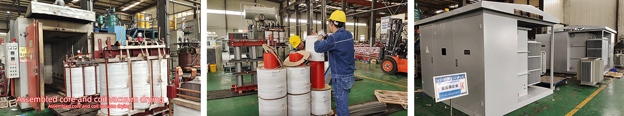
Built for sturdiness and efficiency(Production process)
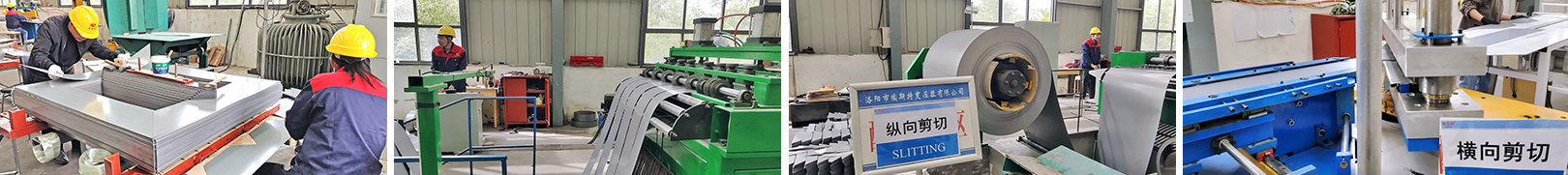
The core
The iron core forms the central element of every transformer. High-grade, cold-rolled metal sheets are precision-cut using computer-controlled machines to ensure compliance with even the smallest tolerances. The individual sheets are then assembled into cores using the step-lap technique by our veteran workers. In this way, weachieve an especially good flux distribution at the joints, resulting in exceptionally low losses and minimal no-load noise.
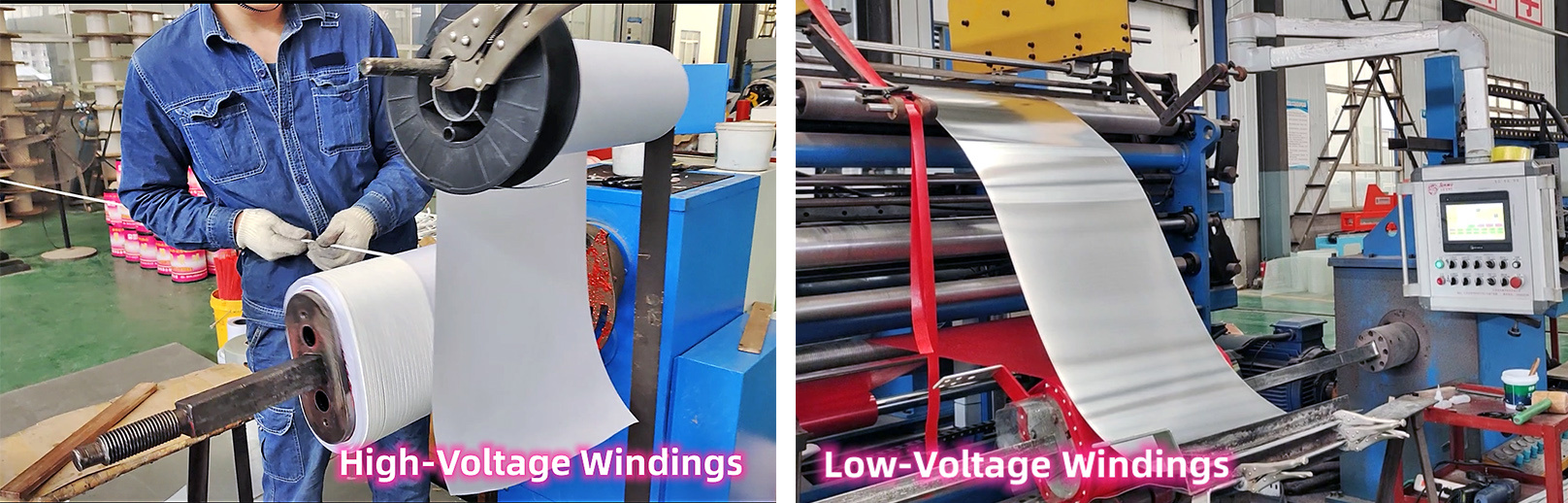
Windings
Transformer windings are subject to extremely high electrical and mechanical stresses and must therefore be protected. The transformer windings of our transformers are made of copper or aluminum. Low-voltage windings are made fromfoil, and high-voltage windings are manufactured from round orstripprofile wire. The use of insulating paper partially coated with epoxy resin (diamond-dotted paper) bonds the winding into a compact block during the drying process and additionally increases the short-circuit capacity.
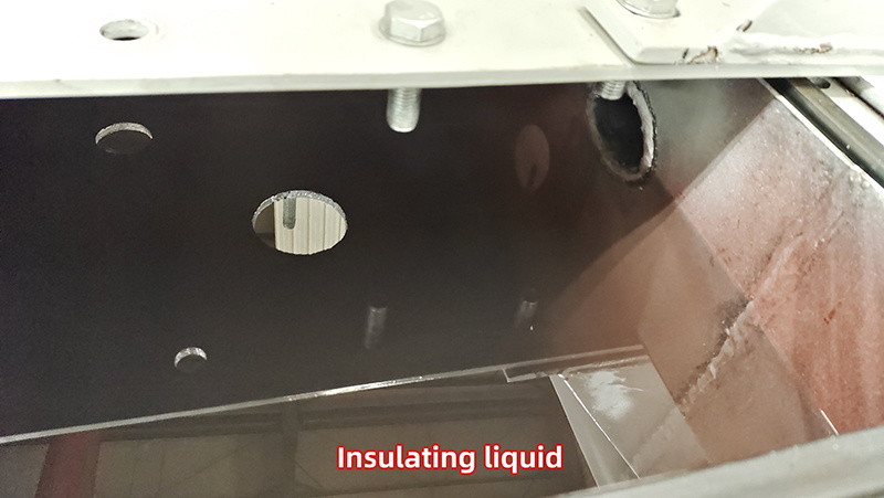
Insulating liquids
The layer insulation is adapted to the alternating voltage strain that occurs in daily operation. Large-scale oil channels are provided to ensure sufficient cooling of the windings and to avoid hot spots. All leads are short-circuit-proof and surge-proof, contributing to the high reliability of thetransformer – and to an above-average service life.
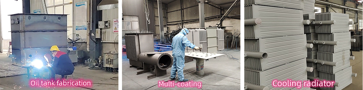
Tank & Cooling
Whether during transport or operation, the tank must remain sealed tight under mechanical stress and regardless of wind or weather. Corrosion protection is especially important. The surface is sandblasted and then multicoated. Upon request, hot-dip galvanization can provide even better protection.
The distribution transformer’s tank must dissipate the entire heat loss. In hermetically sealed transformers, the corrugated walls absorb the changes in the insulation liquid’s volume. Alternatively, the transformer can be designed as an open system or fitted with an oil conservator that compensates for the additional volume.
Some regions also use smooth-walled tanks and built-in radiators. Hermetically sealed units sometimes have an air or gas cushion to compensate for oil expansion. The sheet-steel lid is bolted – or, upon request, welded – to the tank. The steel thickness and the bracing are dimensioned to ensure that the lid withstands all necessary stress.
Final assembly
The transformer’s core-and-coil assembly consists of the core, windings, and connecting cables. High-quality drying and quick filling with insulation oil play a key role in extending the transformer’s service life.Aisite employs the latest techniques. For example, in vacuum low-frequency plants (LFH – low-frequency heating), the process of drying the solid insulation is combined with vacuum drying of the windings through low-frequency heating. The active part is heated by applying low-frequency current (< 1 Hz) to the high-voltage windings with the low-voltage windings short-circuited. While still in the plant, transformers are filled with preheated insulation liquid which is absorbed by the insulation material, thus preventing the intake of oxygen.
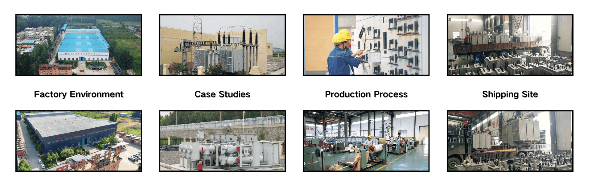
Our Factory
Why Choose AISITE?
Rich Production Experience
With 15-year experience of production and sales, our transformers have been successfully exported to over 50 countries and regions, including Brazil, Tanzania, South Africa, etc.
Full Life-Cycle Support Service
We provide comprehensive technical support at ever stage of operation of your purchased equipment.
Professional Sales Team
Our globally-experienced sales engineers provide tailored power solutions and precise technical guidance, ensuring optional project fit for your specific requirements.
Pursue Innovation and Excellence in Serving Customers
Our technical and sales team are committed to providing customized solutions with cutting-edge technology that solve the toughest challenges facing electricity supply and meet the most stringent needs defined by the industry.
Previous page
Next page
Previous page
Next page
Related products
Related products
Leave a message
Factory Address:500 meters southeast of Yilong Bridge in Yichuan, Luoyang, China